
Technical Q&A, tender clause and downloads
The questions design institutes, EPC contractors and buyers keep asking when they review a copper-clad steel alternative to solid copper, answered as asked; at the end, a tender specification clause you can paste into a technical specification, and downloads. The clauses, constants and worked examples quoted here match the technical guides on this site and can be checked line by line.
Technical Q&A · 14 questions
Selection and design
- Can copper-clad steel replace solid copper in an earthing grid?
- What is the difference between copper-bonded (electroplated) and continuous-cast copper-clad steel?
- How thick should the copper layer be?
- Copper-clad steel is only 25–40 % IACS – will the grid resistance go up?
- How is the cross-section checked to IEEE 80?
- Which soils are unsuitable for copper-clad steel?
Installation and acceptance
- Steel is exposed at cut ends and joints – is there galvanic corrosion?
- What if the copper layer is scratched during installation?
- Does copper-clad steel reduce theft?
- How do we verify copper thickness on delivery?
- Can it be welded to an existing copper grid?
Buying and working with us
Tender specification clause
A specification clause for copper-clad steel earthing conductor written to DL/T 1312-2023, ready to paste into a tender or technical specification: copper thickness, annealed temper, bending, bond and test-report requirements.
Read the clause →Downloads
Evidence: two technical reports (twenty years from 0.25 to 0.6 / 0.8 mm; the earthing-material selection ladder), type-test reports, IEEE P80 contribution
Calculation: sample assessment reports
Product: data sheet, selection guide, ISO certificate
1. Can copper-clad steel replace solid copper in an earthing grid?
Yes, provided two things are done by the book: the copper thickness is chosen from soil corrosion rate × design life (the anti-corrosion standards Q/GDW 12015 and DL/T 2094 and the supervision guide DL/T 2650 agree: 0.25 / 0.6 / 0.8 mm for low / medium / high), and the cross-section is checked for fault-current withstand per IEEE Std 80-2013 clause 11.3.1 with the material constants for the actual conductivity. With both satisfied, copper-clad steel can be used for horizontal and vertical electrodes alike, which is what Chinese national codes and grid-company standards have specified for twenty years. Where it cannot, we say so: extremely corrosive soil combined with a long design life (required copper over 1.0 mm), and 330 kV and larger hub substations (fault current ≥ 50 kA, required section ≥ 240 mm²) – there solid copper or a hybrid grid is the right answer. See "Where CCS can replace solid copper" on the thick-layer page.
2. What is the difference between copper-bonded (electroplated) and continuous-cast copper-clad steel?
Different process, different achievable copper thickness, different final temper. Electroplated: electrodeposited copper, usually 0.25 mm (0.13 mm also on the market), supplied hard – a mature product for driven vertical rods, which we supply too; 0.25 mm-class plated round conductor for horizontal laying also exists in North America – in utility substations and lightning down-conductors outside the NEC's scope; the NEC itself still requires a bare-copper ground ring. Continuous-cast: the steel core passes through molten copper and takes a metallurgically bonded thick layer, 0.25–1.0 mm as specified, which can be fully annealed to a soft temper – the right product for horizontal conductor bent and laid on site. Pressure-bonded / hot-roll clad (the "copper-clad steel wire" of IEEE 80 Table 2) is a third family, mostly used for strand wires. All three are called copper-clad steel in English, so a specification must state the process, the minimum copper thickness at any point and the temper separately – "copper-clad steel, 30 % IACS" on its own specifies nothing.
3. How thick should the copper layer be?
Thickness = corrosion loss over the design life + the layer that must remain at end of life (taken as 0.25 mm). The allowance is calculated per DL/T 2094; where no local data exist, the rates of DL/T 1312-2023 Table 1: negligible 0.001 / weak 0.003 / medium 0.007 / strong 0.012 / extreme 0.017 mm per year, with soil of pH < 4.5 moved up one class (same clause). The standards' resulting classes are 0.25 / 0.6 / 0.8 mm for low / medium / high (Q/GDW 12015, DL/T 2094, DL/T 2650 Table 4). Examples: medium, 30 years: 0.007 × 30 + 0.25 = 0.46 → 0.6 mm; strong, 40 years: 0.012 × 40 + 0.25 = 0.73 → 0.8 mm; extreme, 40 years: 0.017 × 40 + 0.25 = 0.93 → 1.0 mm; extreme, 50 years → 1.1 mm, beyond copper-clad steel – we recommend copper. The soil class is judged from resistivity, pH, salt (chloride) content and moisture; in the assessment we state the class and the basis from the soil data you send.
4. Copper-clad steel is only 25–40 % IACS – will the grid resistance go up?
Grid resistance to remote earth is set by soil resistivity and grid geometry; the conductor's own resistance is negligible in that calculation – the IEEE 80 grid-resistance formulas contain no conductor-material term. Conductivity governs something else: the cross-section needed for fault-current thermal capacity. The simplified formula of IEEE 80 clause 11.3.1, Akcmil = IkA · Kf · √tc, handles it through Kf: copper 7.00, 40 % copper-clad steel 10.45, 30 % copper-clad steel 12.06 – for the same fault current and clearing time, 30 % CCS needs about 1.7 times the section of copper. Example, 20 kA for 1 s: copper 140 kcmil ≈ 71 mm², 40 % CCS 209 kcmil ≈ 106 mm², 30 % CCS 241 kcmil ≈ 122 mm² (1 kcmil = 0.5067 mm²). That is why conductivity must be stated honestly per size (Ø 16 / 0.8 mm is about 27 % – see the calculated table on the Products page): we size with the actual conductivity of each size, not a blanket "30 %".
5. How is the cross-section checked to IEEE 80?
IEEE Std 80-2013 clause 11.3.1 gives two forms: the full equation (37), which yields mm² directly from the material constants, and the simplified Akcmil = IkA × Kf × √tc – its result is in kcmil; multiply by 0.5067 for mm². tc is the fault clearing time in seconds; I is the design current in that conductor – after the split factor and current division within the grid, not the total system fault current. Kf is taken from Table 2 for the listed materials; for a conductivity not in Table 2 (27 %, say) it is calculated from the material constants (resistivity, temperature coefficient, thermal capacity, fusing temperature) with equations 41–44 of clause 11.3.1. Our assessment gives two options – equal diameter (does the existing diameter pass?) and equal short-circuit withstand (a strict match to the original copper section) – with all intermediate figures, so your consultant can recalculate.
6. Steel is exposed at cut ends and joints – is there galvanic corrosion?
Yes, and this is the real weak point of copper-clad steel – it is handled by the joint, not by the conductor. The exposed steel area is small and the surrounding copper area large: a large cathode with a small anode, so the exposed steel corrodes locally and fast. The remedies: ① exothermic welding – the copper alloy fully encloses the conductor end (DL/T 1342-2014 requires the weld to enclose the end faces of the parent conductor completely), so the cut no longer touches soil; ② mechanical connections – seal the end with an epoxy or bituminous coating before burial; ③ never bury a bare cut end, and treat every conductor cut short on site the same way. This is why we supply the moulds and powder and attend the first joints on site. CCS to solid copper: copper on copper, no couple while the layer is intact. CCS to galvanized steel structures: exactly the situation of a copper grid (copper is cathodic to zinc and steel) – handled by normal practice.
7. What if the copper layer is scratched during installation?
A scratch down to the steel is the cut-end case again – local exposed steel corrodes faster, so clean and coat it. Prevention rests on two things: a thick layer resists handling damage (0.8 mm of copper is not 0.25 mm of plating), and an annealed layer does not crack on bending – the DL/T 1312 bend test (horizontal conductor 90° × 3 with no cracking) checks exactly that. Hard, thin-layer rod material tends to crack on the outside of a site bend, which is why we do not recommend hard rod stock for horizontal electrodes.
8. Which soils are unsuitable for copper-clad steel?
"Extreme" soil as DL/T 1312-2023 Table 1 defines it (high class plus pH > 8.5 or < 4.5 and salt > 1.5 %) – for which that standard calls for copper – and long design lives needing more than 1.0 mm of copper: tidal coastal ground, high-chloride saline soil, and acidic soil that lands in "extreme" after the pH < 4.5 upgrade – where the required copper exceeds 1.0 mm we recommend solid copper. Stray-current environments (DC traction, cathodic-protection interference) need a separate assessment: stray-current corrosion attacks copper and copper-clad steel alike, and the copper on CCS is finite. For such projects the assessment report states the conclusion and the basis.
9. Does copper-clad steel reduce theft?
Substantially – it is one of the main reasons utilities have switched. Copper is only about 20 % of the weight (Ø 16 / 0.8 mm: about 0.34 kg of copper in 1.62 kg per metre) and is metallurgically bonded to the steel, so it cannot be stripped and has little scrap value – nothing to attract a copper thief. Copper grids dug out in whole sections, leaving a substation without its earth, have happened in several countries.
10. Which standards apply, and what do your reports cover?
Sizing: IEEE Std 80-2013 (cross-section and Kf), GB/T 50065-2011 (China). Product: DL/T 1312-2023 – the dedicated standard for copper-clad steel earthing conductor, with a power-frequency high-current test and a 500 h salt-spray sequence; our CMA / CNAS dual-stamped type-test reports cover its full programme. United States: UL 467 (listing of rods, clamps and connectors), ASTM B910 (copper-clad steel ground rods), ASTM B227 / B228 (copper-clad steel wire and strand). Lightning-protection components: IEC 62561-2. European substations: EN 50522 / IEC 61936-1. Connectors: IEEE 837, DL/T 1342. The item-by-item comparison is on the Test evidence page.
11. How do we verify copper thickness on delivery?
Per DL/T 1312: on rod or wire, three positions at least 50 mm from an end, three points 120° apart at each, nine points in all, minimum value governs; by the magnetic method (GB/T 4956, identical to ISO 2178) or the microscopical cross-section method (GB/T 6462, identical to ISO 1463). A magnetic thickness gauge does it in minutes, in any laboratory or on site. Each lot (≤ 5,000 m) ships with its factory test report; send a sample to any accredited laboratory, and if it disagrees with our data sheet we pay for the second test.
12. Can it be welded to an existing copper grid?
Yes. CCS-to-copper and CCS-to-CCS joints are exothermically welded with moulds chosen for the two conductor sizes and the same powder as copper-to-copper. Acceptance per DL/T 1342-2014: the weld fully encloses the parent conductor, DC resistance not more than 1.1 times an equal length of parent conductor, tensile strength not below the parent; for US-specification projects connectors can be required to IEEE 837. We supply the moulds, powder and procedure, and attend the first joints on site.
13. Lead time, minimum order and payment?
Standard sizes 2 weeks ex-works (sizes that need a type test first: add the test period, about two months); order to port of arrival about 5 weeks South-East Asia, 7–8 weeks the Gulf, about 10 weeks Europe and the US East Coast. Minimum order 300 m for standard sizes (rods 50 pieces), 1,000 m for non-standard sizes. Quoted FOB Shanghai by default; T/T 30 % deposit, 70 % before shipment. See "Supply, capacity and lead time" and "Ordering terms" on the Products page.
14. How does the free assessment work?
Send the conductor size and length, soil data (resistivity, pH, salt / chloride), design fault current and clearing time, and design life; within 24–48 hours you receive two options (equal diameter / equal short-circuit withstand), the basis for the copper thickness, the IEEE 80 section check, and the copper saved in tonnes and dollars, signed by the chief engineer. Request it here.
Tender specification clause – copper-clad steel earthing conductor (paste into your technical specification)
Fill in the square brackets for the project. The clauses follow DL/T 1312-2023, IEEE Std 80-2013 and DL/T 1342-2014 and name the US / IEC equivalents; your consultant can check, cut or amend each one.
- Material and process – Earthing conductor shall be copper-clad steel: a low-carbon steel core with a copper layer metallurgically bonded by continuous casting; copper purity ≥ 99.9 %; horizontal electrodes and earthing conductor in annealed (soft) temper, vertical rods may be hard-drawn. Non-metallurgical cladding such as sleeve cold-drawing is not acceptable (DL/T 1312-2023 clause 4.2).
- Copper thickness – Minimum copper thickness at any point not less than [0.6 / 0.8 / 1.0] mm, determined from the soil corrosion class and a design life of [__] years (per Q/GDW 12015-2020 / DL/T 2094-2020 and DL/T 2650-2023 Table 4); measured per DL/T 1312 clause 7 (nine points, minimum governs) by ISO 2178 (magnetic method) or ISO 1463 (microscopical method).
- Conductivity – Relative conductivity at 20 °C not less than [25] % IACS (stated as a DL/T 1312 grade 15 / 20 / 25 / 30 / 40; tested per IEC 60468 or GB/T 3048); the tender shall declare the actual conductivity of each size, and the cross-section check shall use the actual value.
- Mechanical properties – Tensile strength: horizontal electrodes and earthing conductor ≥ 300 N/mm², vertical rods ≥ 550 N/mm²; bend: horizontal conductor 90° × 3 without cracking of the copper layer; bond: no separation of copper from steel after the torsion / hammer test.
- Cross-section – Checked per IEEE Std 80-2013 clause 11.3.1 (the Table 2 Kf simplified form, which gives kcmil, or the full equation (37) from material constants), for a design current of [__] kA and a clearing time of [__] s. [Projects in China: per GB/T 50065-2011 / DL/T 1312 Annex C.]
- Type tests – The supplier shall submit type-test reports to the full DL/T 1312-2023 programme issued by a CNAS (ILAC-MRA) accredited laboratory, including the power-frequency high-current test (90 % of fusing current × 3, ΔR ≤ 5 %) and the electrical–corrosion sequence (≥ 25 current–temperature cycles at 350 °C, 10 freeze–thaw cycles, ≥ 500 h neutral salt spray, high current; ΔR ≤ 10 % per stage, ≤ 30 % overall). Sizes offered without a report shall be type-tested and reported before delivery. [Optional: IEC 62561-2 / UL 467 test reports in addition.]
- Routine tests – Each lot (same model, size and temper, ≤ 5,000 m) shall be delivered with a factory test report (copper thickness, surface, tensile, bend, resistivity); the purchaser may witness the tests or have samples retested at any accredited laboratory.
- Joints – Exothermic welding per DL/T 1342-2014 / IEEE 837: the weld shall fully enclose the conductor end faces, DC resistance ≤ 1.1 times an equal length of parent conductor, tensile strength ≥ parent conductor; every cut end shall be buried only inside a weld or after corrosion-protective coating. The supplier shall provide moulds, powder and the welding procedure.
- Marking and documents – Each reel marked with the model code (DL/T 1312 format, e.g. CCS CC 25-0.8-Φ16), lot number and length; delivered with the type-test reports, the lot test report, raw-material certificates and a copy of the ISO 9001 certificate.
- Equivalent standards – For ground rods and connectors, UL 467 listing or IEC 62561-2 test reports are acceptable; for horizontal earthing conductor the type-test reports of clause 6, or equivalent tests approved by the purchaser, shall be submitted.
Downloads
| Document | Note | |
|---|---|---|
| The evidence: what twenty years of Chinese practice and the standards sayFor review by design institutes, consultants and owners – every clause quoted | ||
| Why did China's copper-clad steel horizontal earthing move from 0.25 mm to 0.6 / 0.8 mm?Technical report TR-01, Copper-Clad Steel Earthing in China · English 9 pp / Chinese 7 pp | From ERICO's 0.25 mm plated product to five standards – DL/T 1312, Q/GDW 10466, DL/T 2094, Q/GDW 12015, DL/T 2650 – writing down "0.6 mm medium / 0.8 mm high corrosivity, horizontal conductor annealed". With the copper corrosion-rate and 30-year allowance table, the three-level comparison and acceptance practice | English · 中文 |
| Galvanised steel, copper-clad steel or copper – how do you choose by soil?Technical report TR-02, Corrosion-Resistant Earthing Materials in China · English 9 pp / Chinese 7 pp | From galvanised grids rusting through, past zinc-clad, stainless, nano-carbon coatings and graphite rope, to the four-step ladder DL/T 2650-2023 fixed by soil corrosivity. With the 110 kV line failure case from Annex E, the three-standard ladder comparison and the conditions of use for each material | English · 中文 |
| Which tests has our product passed?Ø 12 / 0.6 mm continuous-cast CCS type-test report · English · CNAS (ILAC-MRA) · 8 pages · 1.9 MB | Report CT2025070054-CPB01, type CCS CC 20-0.6-Φ12, full DL/T 1312-2023 programme: copper layer 0.60–0.61 mm, tensile 484–489 N/mm², conductivity 31 % IACS, 350 °C × 25 cycles → freeze-thaw → 500 h salt spray → 5.38 kA high current, final resistance change 0.2–0.4 % (limit 30 %). Other sizes on request | Download · Other sizes |
| What did we propose to the IEEE 80 working group?IEEE P80 technical contribution, proposed unified definition of copper-clad steel · September 2026 | Defines copper-clad steel as "steel core plus bonded copper layer", covering electroplated, cast and pressure-bonded processes; submission available on request | Request |
| The calculation: what the free assessment gives youTwo sample reports showing the content and method of a sizing report | ||
| A 110 kV coastal substation – how is a copper grid replaced with copper-clad steel?Copper vs CCS earthing assessment, sample report · English 4 pp / Chinese 3 pp | Hypothetical case: soil class and copper-thickness derivation, IEEE 80 full-equation and Kf checks, equal-diameter and equal-withstand options, copper quantity, test evidence, exclusions. Ready to forward to the design institute or the owner's consultant | English · 中文 |
| The product: data, selection and credentialsFor procurement and submittals | ||
| Conductivity, resistance and mass by size – and how to orderProduct data sheet · English 4 pp | Range and model code, materials and construction, calculated values by size (IEEE 80 Table 1 constants), copper-thickness selection, type and routine tests, standards, packing and ordering terms | Download |
| The complete selection method, from definition to exothermic weldingCopper-Clad Steel Grounding System Selection Guide, 2026 edition · Chinese 24 pp 2 MB | The eight-part design guide of this site bound as one document; the English content is in the guide pages on this site | Download |
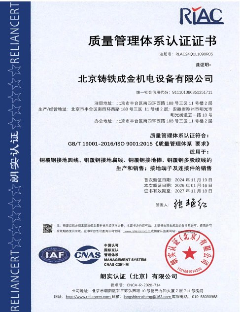
| Quality management certificationISO 9001:2015 certificate | Certificate RLAC24Q1L1090R0S, valid to 18 Nov 2027 | Download |
Have a project in mind?
Send the conductor size, length, soil and fault current – two sizing options and the copper saving come back within 24–48 hours, free.
Request the free assessmentJust a quotation