
Our focus: thick-layer, annealed copper-clad steel – the replacement for solid-copper grids
The common international product – a 0.25 mm plated, non-annealed hard rod – is a mature and sensible choice for a vertical electrode driven deep into the ground. We supply it too, with matching type-test reports. But to replace a solid-copper grid horizontally, thin and hard is not enough: the layer is too thin to cover a lifetime of corrosion loss in medium- and high-corrosivity soil and still carry fault current, and the hard temper is difficult to bend on site. So what we lead with is a conductor that has both: a thick copper layer (Chinese power-sector standards, validated over millions of kilometres, settled on 0.6 mm for medium-corrosion and 0.8 mm for high-corrosion soil) and an annealed, soft temper. Annealing is not our invention; it is the conclusion of more than a decade of Chinese field experience. The power-industry product standard for copper-clad steel earthing (DL/T 1312) said nothing about temper in its 2013 edition; the 2023 revision recommends annealed material for horizontal conductors. The State Grid corporate standard (Q/GDW 10466-2021) makes the same recommendation. China's two principal copper-clad steel standards, each revised independently, arrived at the same answer. Continuous casting delivers both: it can lay down a thick layer, and the finished conductor can be fully annealed. Thick-layer soft wire for the horizontal grid plus thin-layer hard rods for the vertical electrodes make up a complete earthing system.
| Parameter | 0.6 mm layer | 0.8 mm layer | 1.0 mm layer |
|---|---|---|---|
| Soil corrosivity (per standard selection) | Medium | High | High, longer design life |
| Typical application | PV plants, telecom sites, general industry | Substations, transmission, rail, chemical plants | Most aggressive soils, longest design life |
| Copper purity | ≥ 99.9 % | ||
| Copper layer at any point | ≥ 0.60 mm | ≥ 0.80 mm | ≥ 1.00 mm |
| Tensile strength | Horizontal conductor ≥ 300 N/mm² (annealed); vertical rod ≥ 550 N/mm² | ||
| Available forms | Round wire / flat tape / ground rod | ||
Design logic: the copper layer is both corrosion allowance and current-carrying layer. Thickness = corrosion loss over the design life + the residual layer still needed for conductivity at end of life. Where the soil is extremely aggressive the standards call for solid copper – and we will say so.
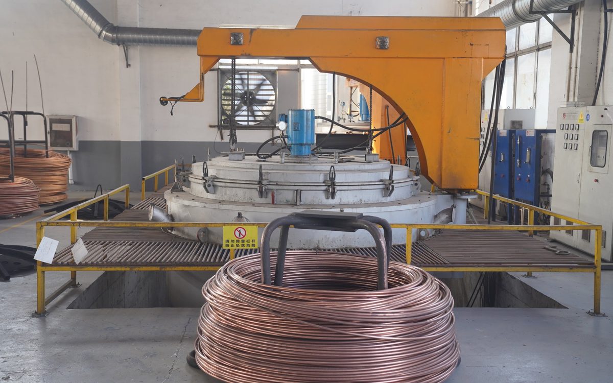
Where the annealing happens: the pit-type furnace at our Anhui plant, where continuous-cast round wire is annealed by the whole coil to a soft temper – the source of the "annealed" in "thick-layer, annealed", and the step a hard plated rod cannot take.
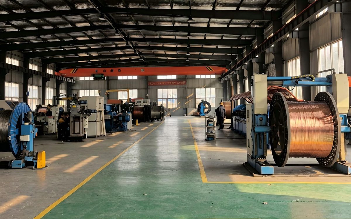
The difference shows on site: soft-temper round wire bends by hand to the radius the layout needs without cracking the copper (DL/T 1312 bend test: 90° × 3, no cracks); hard rod stock tends to crack on the outside of the bend.
What it saves – Ø 16 mm conductor, copper at US$ 14,800 / t
Option 1Equal diameter – when the original copper design has spare margin
| Conductor | Cu kg/m | Copper saved | Copper value saved / km* |
|---|---|---|---|
| Ø 16 solid copper | 1.80 | — | — |
| Ø 16 CCS, 0.6 mm | 0.260 | ≈ 86 % | ≈ US$ 22,800 |
| Ø 16 CCS, 0.8 mm | 0.342 | ≈ 81 % | ≈ US$ 21,600 |
| Ø 16 CCS, 1.0 mm | 0.422 | ≈ 77 % | ≈ US$ 20,400 |
Option 2Equal short-circuit withstand – sized per IEEE Std 80
| Conductor | Cu kg/m | Copper saved | Copper value saved / km* |
|---|---|---|---|
| 120 mm² copper strand (between 4/0 AWG and 250 kcmil, 107–127 mm²) | 1.08 | — | — |
| Ø 16 CCS, 1.0 mm (≈ 32 % IACS) – equal short-circuit withstand to 120 mm² | 0.42 | ≈ 61 % | ≈ US$ 9,700 |
| Ø 16 CCS, 0.8 mm (≈ 28 % IACS) – equal short-circuit withstand to ≈ 110 mm² copper strand (0.99 kg/m) | 0.34 | ≈ 65 % | ≈ US$ 9,500 |
* Value of the copper itself, at LME US$ 14,800 / t (10 Sep 2026); excludes steel core, processing, freight and joints. Every US$ 1,000 / t change in copper moves these figures by about 7 %. Your assessment is recalculated at the LME price of the day. Conductivity depends on diameter (see the technical data on the Products page): at ≈ 28 % IACS, Ø 16 / 0.8 mm corresponds in short-circuit withstand to about 110 mm² of copper; for a strict match to 120 mm² use Ø 16 / 1.0 mm (≈ 31 %) or let the assessment size it from the actual constants. "Fault current" in the envelope table is the design current of the grid conductor (after the split factor and current division within the grid), not the total system fault current.
Where CCS can replace solid copper – and where it cannot
| Application | Fault current @ 1 s / typical copper size | Replaceability |
|---|---|---|
| ★ PV plants, telecom sites, industrial plants, rail | ≤ ~20–25 kA / 50–95 mm² | Fully replaceable – Ø 12–14 round wire, easiest to install. The largest segment by kilometres laid. |
| Distribution and 220 kV substations | ≤ ~33 kA @ 1 s (≈ 40–47 kA @ 0.5 s) / 70–120 mm² | Replaceable – Ø 14–16 round wire (Ø 16 is the practical limit for bending on site). |
| 330 kV and above, major transmission hubs | ≥ ~50–63 kA / ≥ 240 mm² | Generally not – solid copper or a hybrid grid is the right answer, and we will tell you so. |
Three ways to buy – what each one leaves you to arrange
Who provides each of the four things a copper replacement needs, by purchasing route.
| What you need | Buying through a trader | Buying product only | Beijing Zhutiechengjin |
|---|---|---|---|
| Thick-layer (0.6 / 0.8 mm) horizontal conductor | Depends on the source | As per the specification ordered | ✓ Continuous-cast 0.6 / 0.8 / 1.0 mm, annealed |
| Equal-withstand sizing report per IEEE 80 | Arranged separately | Arranged separately | ✓ Two options (equal diameter + equal short-circuit withstand) |
| Type-test reports under a fault-current test sequence | Factory report passed on | Depends on the factory | ✓ CMA/CNAS dual-stamped, run under a fault-current sequence |
| Exothermic welding consumables and site guidance | Sourced separately | Depends on the factory | ✓ Moulds, powder, procedure, on-site guidance |
| Who signs for the sizing | You / your consultant | You / your consultant | ✓ Chief engineer signs, and is your direct contact |
Have a project in mind?
Send the conductor size, length, soil and fault current – two sizing options and the copper saving come back within 24–48 hours, free.
Request the free assessmentJust a quotation