
Chemical / coal-chemical / oil & gas
Copper-clad steel grounding system solutions · 5 of 8
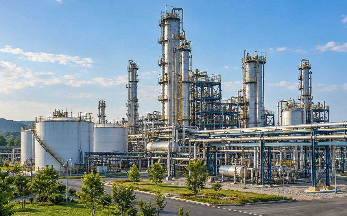
Illustrative application scene (AI-generated), not a project photograph.
1 Combination: intake substation + building rings + CP
Combination: intake substation + building rings + cathodic-protection coordination. The plant intake substation (110 / 220 kV) follows the substation mesh grid; every building, process unit, tank farm and stack gets a ring electrode with rods at the corners and at equipment, bonded to the foundation reinforcement, the rings interconnected about every 20 m into one plant grid – thermal, coal-chemical and refinery sites are all built this way.
Building ring earthing (basic form ③) in brief: the aim is to hold the potential of metal enclosures under 50 V during a fault; ring buried ≥ 0.6 m deep and ≥ 1 m from the wall, 2.4–3 m rods at the corners, welded to the foundation reinforcement at two points or more; down-leads coated for corrosion within 30 cm of the soil–air boundary.
Pipelines and tank farms usually carry cathodic protection; the galvanic interaction between copper-surfaced electrodes and the CP system has to be coordinated at design stage (DL/T 2094-2020 clause 5.2.6); exothermic welding in hazardous areas falls under hot-work control.
2 Intake substation and the plant grid
Refineries, coal-chemical plants, thermal power stations and large gas gathering stations share one earthing structure: an intake substation grid built to substation rules, plus a ring electrode around every building, process unit and tank farm, all rings interconnected about every 20 m into one plant-wide grid.
- The intake substation (110 / 220 kV) follows the substation page: single-phase fault current sets the section, Ø 14–16, 0.8 mm, step and touch checked per IEEE 80.
- With the plant tied into one grid, the substation's GPR reaches every building – good (no potential differences inside the plant) and a risk (the plant boundary, and pipelines and communication lines leaving the site, carry it out). IEEE 80 clause 17, transferred potential: insulating flanges on metal pipelines leaving the site, fibre or isolating transformers on communication lines.
- Structural steel, pipe racks and equipment foundation reinforcement in the process areas are natural electrodes and are all bonded to the rings; thermal plants bond every column footing.
3 Building ring plus rods (basic form ③)
The simplest of the three basic forms, and the most often neglected. Its target is not earth resistance but personal safety: holding the potential of metal enclosures under 50 V during a fault so the protective device trips reliably.
Basic form ③: building ring plus corner rods (bonded to foundation rebar; add radials or lead out if R is too high)
- Criterion: GB/T 50065-2011 eq. 7.2.7 for TT systems, RA ≤ 50 / Ia, Ia being the operating current of the protective device (IΔn for an RCD). A TN-S system returns fault current through the PE conductor, but a broken PE turns it into TT, so the PE still gets a local earth at the building.
- Layout: a ring ≥ 1 m outside the wall, ≥ 0.6 m deep; Ø 14–16 × 2.4–3 m rods at the corners and near the main switchboard and large motors, spaced ≥ 2 rod lengths (closer, they shield each other); welded to the foundation reinforcement at two points at least.
- Material: plant soils are contaminated with process media (acid, alkali, salt, oil) and will not be dug up for inspection in 30 years: horizontal electrodes 0.6/0.8 mm copper-clad steel; rods can be 0.25 mm copper-bonded (driven vertically, not bent, and rod corrosion concentrates at the soil–air line at the top).
- Down-leads: coated or heat-shrunk for 30 cm around the ground line – the first point in the system to rust through.
4 Building earthing calculator
Ring plus rods: resistance and the GB/T 50065 eq. 7.2.7 check
Ring by the GB/T 50065 Annex B horizontal-electrode formula (shape coefficient 0 for a closed ring); rods by ρ/(2πl)·ln(4l/d), parallel utilisation 0.7. Ia: enter IΔn for an RCD (0.03 / 0.1 / 0.3 / 0.5 A), or 5–10 × rated current for a breaker's instantaneous trip.
5 Lightning, static and shared earthing
- Lightning: GB 50057 asks ≤ 10 Ω for the separate air-termination earths of class I and II structures; tank farms, flares and stacks by their own class.
- Static: petrochemical codes ask ≤ 100 Ω for static earthing – the easiest target on the site.
- Shared earthing: GB 50057 sets the resistance of a shared earthing system at the lowest of the systems sharing it, so once the plant is one grid the governing design is the IEEE 80 check of the intake substation, not 10 Ω or 100 Ω. Each discipline driving its own rods and proving its own 4 Ω is the commonest waste on a plant site.
6 Cathodic-protection coordination
Oil and gas fields, pipelines and tank bottoms mostly carry cathodic protection. A copper-surfaced electrode in soil is a cathode and draws CP current: the CP system is "underfed", and the copper-to-steel couple accelerates pipeline corrosion at coating defects. DL/T 2094-2020 clause 5.2.6 requires copper earthing and CP to be coordinated at design stage. Three approaches:
- Insulating flange plus spark gap / DC decoupler between pipeline and plant grid – conducting at power frequency and lightning, isolating at DC. The usual answer.
- Allow for the electrode's current drain in the CP capacity – workable on small sites.
- Zinc-clad or galvanised steel electrodes inside the CP influence zone (permitted in low-corrosivity sections by the DL/T 2650-2023 ladder), trading life for potential compatibility – only where isolation is impossible.
7 Process corrosion and hot-work control
Plant soil corrosivity follows the process, not the geography: around pickling, brine and chlor-alkali units the pH can reach 3–4 and Cl⁻ thousands of mg/kg – the same order as the 110 kV line failure in DL/T 2650 Annex E (Cl⁻ 3930 mg/kg, pH 8.57, cold-galvanised 2.3–13.2 μm, rusted through in a few years). Horizontal electrodes 0.8 mm or copper in such areas; Q/GDW 12015 5.2.2.6: pH ≤ 4.5 → ≥ 1.0 mm.
Exothermic welding in process areas is hot work and falls under the plant's permit system; our practice is to prefabricate every joint that can be made in the warehouse (structure bonds, transitions, down-lead terminals), leave only the unavoidable welds inside the units, and schedule them for turnarounds. Where no hot work is possible, high-pressure compression terminals replace the weld.
8 What to send
Plot plan (intake substation, process units, tank farms, pipeline entry points), intake voltage and fault current, soil resistivity and pH / Cl⁻ (or a description of the process media), the cathodic-protection scheme, hazardous-area classification drawing, design life.
At a glance: typical selection
| Project type | Governing factor | Typical fault current / copper size | Soil and environment | Copper layer | Sizes (horizontal / vertical) | Replaceability |
|---|---|---|---|---|---|---|
| Chemical / coal-chemical / oil & gas | Thermal + high corrosion + CP interference | High at plant intake / 95–120 mm² | Acid, alkali and salt-contaminated soil, low pH | 0.8–1.0; pH < 4.5 one class up | Ø14–16 wire / Ø20 rods | Replaceable; copper where extreme |
Have a project in mind?
Send the conductor size, length, soil and fault current – two sizing options and the copper saving come back within 24–48 hours, free.
Request the free assessmentJust a quotation