
Rail and metro
Copper-clad steel grounding system solutions · 7 of 8
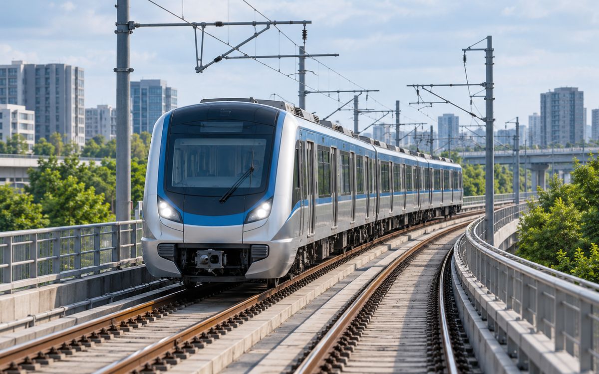
Illustrative application scene (AI-generated), not a project photograph.
1 Combination: running earth conductor + traction substations
Combination: running earth conductor (its own class) + traction substations along the line. The running earth conductor links traction substations, wayside equipment and stations along the track; stray-current corrosion is its own problem, hence 0.8 mm throughout. Traction, AT and sectioning substations follow the substation mesh grid, with large traction fault currents, a 30-year-plus life requirement and often poor corner sites.
2 The running earth conductor: a class of its own
The integrated earthing system of an electrified railway ties traction substations, wayside signalling, communication and power equipment, catenary masts and the reinforcement of bridges and tunnels to one earth conductor running the length of the line, an electrode tens to hundreds of kilometres long. It is neither a substation mesh nor a tower radial but a fourth form, with three characteristics:
- Resistance is not the issue; section and continuity are. An electrode hundreds of kilometres long has a very low resistance (the integrated system asks ≤ 1 Ω, met almost automatically); the real requirements are the conductor's current rating – Chinese practice calls for a copper-equivalent section ≥ 35 mm² – and the reliability of every connection along the line.
- Current flows permanently. Part of the traction return flows through the earth conductor, so it carries current all the time, not only during faults as a substation grid does; under AC traction this is induced and return current, under DC metro traction it is stray current.
- Laid in cable troughs or the formation, never dug up in 30 years. Once laid it runs with the line; replacement means a possession.
So the material of the running earth conductor is chosen for life, not soil: copper cable (stolen) or 0.8 mm copper-clad steel strand or wire.
3 Traction and AT substations
Traction, autotransformer and sectioning substations are walked through the substation page, with three differences:
- Large fault currents. 25 kV traction-network faults of 10–25 kA, and with single-phase or V/x traction transformers the whole fault current returns through the grid; section by IEEE 80 eq. 37, Ø 14–16, 0.8 mm.
- Poor sites. Traction substations sit on corner plots beside the line, small and with poor soil, so resistance is hard to meet; reduce it in the order of section 5 of the substation page – extend, lead out (the line corridor is a ready-made route), long vertical electrodes.
- Connection to the running earth conductor. The substation grid is tied to it at two points at least, so the substation's GPR is shared along the line; but every wayside device then sees that potential, and the step and touch check per IEEE 80 has to treat the running conductor as part of an interconnected grid.
4 Metro: stray current decides everything
Metros return DC 1500 / 750 V traction current through the running rails; rail-to-earth insulation is never perfect and part of the return flows through the ground – stray current. Wherever it leaves reinforcement, pipes or electrodes it causes electrolytic corrosion, about 9 kg of steel per ampere-year. The logic is the reverse of a railway: insulate the rails from earth as far as possible, collect the stray current with the structural reinforcement as a drainage mat and return it to the negative bus, and make the electrodes able to withstand its discharge.
- Electrodes at stations, in running tunnels and at bulk substations lie in the stray-current zone; galvanised steel is electrolysed away in a few years, and pure copper or 0.8 mm copper-clad steel is the only 30-year choice.
- The 110 kV bulk substation follows the substation page; traction and step-down substations are mostly underground or semi-underground, in pure copper per DL/T 2650-2023 5.1.1.7, with copper-clad steel for outdoor parts and depots.
- Depots and stabling yards, large and full of equipment, take the most copper-clad steel in a metro: a yard grid plus a ring (basic form ③) around every shed.
5 Material: why 0.8 mm
Rail electrodes share three conditions: permanent current, no possibility of excavation, and a stray- or induced-current environment. The 0.8 mm step of DL/T 2650-2023 Table 4 corresponds to high corrosivity, and stray-current zones fall under Q/GDW 12015 clause 4.8, "important sites ≥ 0.8 mm or copper". We do not supply 0.25 mm or 0.6 mm buried horizontal electrodes for rail projects. Strand is used for the running earth conductor and for connections that must bend (position 2: strand is continuous-cast only).
6 What to send
Traction system (AC 25 kV / DC 1500 V), substation positions and fault currents, the running-conductor section requirement (copper equivalent), the stray-current protection scheme (metro), whether substations are underground, typical resistivity along the line, design life.
At a glance: typical selection
| Project type | Governing factor | Typical fault current / copper size | Soil and environment | Copper layer | Sizes (horizontal / vertical) | Replaceability |
|---|---|---|---|---|---|---|
| Rail and metro (running earth conductor) | Stray-current corrosion, continuity | Traction return / 70–120 mm² | Varies; urban fill | 0.8 | Ø12–16 wire / Ø16 rods | ★ Fully replaceable; our core track record |
Have a project in mind?
Send the conductor size, length, soil and fault current – two sizing options and the copper saving come back within 24–48 hours, free.
Request the free assessmentJust a quotation