
Transmission-line towers
Copper-clad steel grounding system solutions · 2 of 8
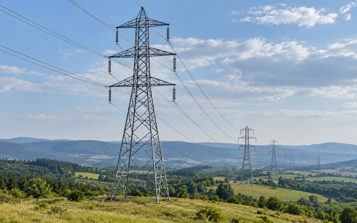
Illustrative application scene (AI-generated), not a project photograph.
Basic form ②: tower loop plus radials (one rod at each loop corner and at each radial end)
The principle first: Earth resistance depends only on the shape and area of the electrode and the soil resistivity, not on the material; the material decides the service life. Tower earthing shows this better than anything: its job is lightning, its shape rule is "radials before meshes", and its material rule is "copper-clad steel because of theft and corrosion". Formulas per the annex of GB/T 50065-2011 and the construction code GB 50169.
1 What this project has to achieve
A tower earthing installation has a different job from a substation grid:
- Lightning comes first. When lightning strikes the tower top, the lower the footing resistance the lower the tower potential and the smaller the chance of back-flashover across the insulator string. What counts is the impulse resistance, not the power-frequency value; beyond a certain length the far end of a radial contributes nothing to it.
- Power-frequency fault current is small. A line-to-earth fault is shared along the shield wire among neighbouring towers; each tower sees little, and the conductor section is set by mechanical strength and impulse, not thermal stability.
- Step voltage is usually not checked. Remote hill towers can use cross or radial layouts directly; towers in residential areas and paddy fields get a closed ring around the footing (GB 50169 clause 3.7.7).
- The real enemies are variable soil and theft. Along one line resistivity can vary a hundredfold from river flat to hilltop, and theft of copper radials is the leading cause of line earthing failure.
2 Permitted earth resistance
GB/T 50065-2011 Table 5.1.3 (power-frequency footing resistance of towers on lines with shield wire), consistent with GB 50169 clause 3.7, graded by soil resistivity:
| Soil resistivity ρ (Ω·m) | ≤ 100 | 100–500 | 500–1000 | 1000–2000 | > 2000 |
|---|---|---|---|---|---|
| Maximum power-frequency resistance (Ω) | 10 | 15 | 20 | 25 | 30 |
| Practice (GB 50169 clause 3.7) | in moist areas the natural earthing of tower and footing may suffice | add an artificial electrode, depth ≥ 0.6 m | horizontal electrodes, depth ≥ 0.5 m | depth ≥ 0.3 m; where 30 Ω is hard to reach, 6–8 radials totalling not more than 500 m, or continuous counterpoise | |
Maximum length of each radial (GB 50169 Table 3.7.5): 40 m at ρ ≤ 500 Ω·m, 60 m at ≤ 1000, 80 m at ≤ 2000, 100 m at ≤ 5000. Beyond that length a radial adds nothing to impulse resistance and is pure waste. Where low-resistivity ground lies within 1.5 radial lengths, part of the electrode may be led out to it (clause 3.7.6).
3 Radial electrodes: formula and design table
Power-frequency resistance of a horizontal electrode (annex of GB/T 50065-2011):
L is the total electrode length, h the depth, d the conductor diameter (half the width for flat tape) and A the shape coefficient: straight −0.6, L-shape −0.18, three radials 0, four radials 0.48, six radials 1.69, eight radials 2.91.
Design table: four radials, Ø 12 wire, depth 0.6 m; the shortest radial that meets Table 5.1.3 by the formula above (conservative – the natural earthing of the footing is ignored):
| Soil resistivity (Ω·m) | 100 | 300 | 500 | 1000 | 2000 | 3000 |
|---|---|---|---|---|---|---|
| Length of each radial S (m) | 5 | 11 | 19 | 30 | 52 | 66 |
| Total length 4S (m) | 20 | 44 | 76 | 120 | 208 | 264 |
| Calculated resistance (Ω) | 9.1 | 14.1 | 14.7 | 19.9 | 24.6 | 30.0 |
| Limit (Ω) | 10 | 15 | 15 | 20 | 25 | 30 |
In moist ground at ρ ≤ 100 Ω·m the natural earthing of the four footings usually meets 10 Ω and no electrode is needed. Above 3000 Ω·m, once radials are laid to the Table 3.7.5 limit, no hard resistance requirement applies and insulation coordination takes over.
Radial electrode – quick calculator
Uniform soil, power-frequency resistance; impulse resistance is derived with an impulse coefficient. Radials should not exceed the limits of GB 50169 Table 3.7.5. For preliminary judgement, not a substitute for the design report.
What design-institute drawings actually show: loop plus radials
Typical Chinese line drawings are not pure radials but a footing loop plus radials: a square loop of side H = 10–20 m around the four footings (grading, and bonding the natural earthing), with radials L = 0–100 m from the corners, graded by soil resistivity. The loop takes part of the dissipation, so radials are shorter than in a pure-radial scheme at the same resistivity. One rod at each corner of the loop – the corners carry the highest current density and the rods grade potential there; one more at the end of each radial – the end is where a rod lowers resistance most, and it also anchors the radial in the trench so a thief cannot pull it out whole (omitted where rock will not take it). Two selection tables from real projects:
| Type | Soil resistivity (Ω·m) | Permitted R (Ω) | Loop side H (m) | Radial length L (m) | Total length (m) |
|---|---|---|---|---|---|
| TF1 | 100 | 10 | about 12 (loop + leg connections) | 0 | 49 |
| TF3 | 300 | 15 | 2 | 57 | |
| TF5 | 500 | 15 | 13 | 101 | |
| TF10 | 1000 | 20 | 26 | 153 | |
| TF20 | 2000 | 25 | 50 | 249 | |
| TC6 | 600 | 20 | 20 | 0 | — |
| TC10 | 1000 | 20 | 15 | — | |
| TC15 | 1500 | 25 | 23 | — | |
| TC20 | 2000 | 25 | 39 | — |
From the earthing drawings of two Chinese 220 kV line projects (with a 20 m loop no radials are needed below 600 Ω·m). Compare with the pure-radial design table above: the larger the loop and the better the footing's natural earthing is used, the shorter the radials.
Scale: in one provincial utility's 2009 critical-grid retrofit programme, eight supply bureaus rebuilt the earthing of about 2 000 towers on 110–220 kV lines with roughly 1.98 million metres of Ø 8 copper-clad steel wire – little per tower, but many towers, so a whole line uses far more material than a substation. A new ±800 kV DC or 1000 kV AC UHV line takes about RMB 20–40 million of copper-clad steel earthing including installation.
4 Order of measures and common mistakes
- Use the natural earthing first: all four legs and the footing reinforcement bonded to the electrode (GB 50169 clause 3.7.11).
- Then radials: as few and as straight as possible; long and short combined, trenched along contour lines. The cross is the most common and most economical layout.
- Lead out: where river flats or farmland lie within 1.5 radial lengths, lead part of the electrode there – far better than lengthening in place.
- Not used: driving rods into rocky hillsides (they will not go in and shield each other), and "reducing resistance" with chemical backfill or block electrodes (brief effect, long corrosion, least efficient shape, banned by most utilities). A dense 3 m × 3 m mesh around the footing grades potential but does almost nothing for resistance.
5 Material and theft
Tower electrodes are shallow, unattended and run through changing soil; they face two problems, corrosion and theft.
- Corrosion: by the DL/T 2650-2023 ladder – hot-dip galvanised round steel in negligible and low corrosivity sections; 0.6 mm copper-clad steel in medium; 0.8 mm in saline and acidic sections. The 110 kV line case in Annex E of the guide: cold-galvanised flat steel of 2.3–13.2 μm in high-corrosivity soil, down-lead rusted through, recommendation copper or > 0.8 mm copper-clad steel.
- Theft: stolen copper radials are the main reason lines switch to copper-clad steel. Copper is about 20 % of its weight, metallurgically bonded and cannot be stripped; scrap value is negligible.
- Sizes: radials Ø 10–12 annealed wire (bent along contours on site), vertical rods Ø 14–16 only where the ground allows, down-leads exothermically welded or clamped to the legs.
6 Installation and acceptance
- Trench along contour lines on slopes, no negative tolerance on depth, stones removed and backfill compacted (GB 50169 clause 3.7.9).
- Every leg connected to the electrode; the leg connection made so it can be opened for measurement (clauses 3.7.10, 3.7.11).
- Measurement: fall-of-potential with probe leads at least 4–5 radial lengths long – short leads are the usual origin of lines where "every tower passed".
- Where the drawing cannot be followed, an as-built sketch with positions and sizes (clause 3.7.8).
7 What we can do
- Section-by-section design: radial layout, length and calculated resistance for every tower from its soil resistivity, output as a design table; lead-out or counterpoise schemes for high-resistivity sections.
- Section-by-section material: galvanised steel / 0.6 / 0.8 mm copper-clad steel by corrosivity section, output as a bill of materials.
- Complete supply: Ø 10–12 annealed wire on reels, rods, exothermic moulds and powder, leg connectors.
Send: line voltage, number of towers and soil resistivity by section, required resistance, design life, soil corrosivity along the route (or general terrain).
At a glance: typical selection
| Project type | Governing factor | Typical fault current / copper size | Soil and environment | Copper layer | Sizes (horizontal / vertical) | Replaceability |
|---|---|---|---|---|---|---|
| Transmission-line towers | Footing resistance, lightning impulse, theft | Small per tower after sharing / Ø10–12 counterpoise | Varies along the route; high-resistivity hills | 0.6; 0.8 in saline / acidic sections | Ø10–12 radials / Ø14–16 rods | ★ Fully replaceable |
Have a project in mind?
Send the conductor size, length, soil and fault current – two sizing options and the copper saving come back within 24–48 hours, free.
Request the free assessmentJust a quotation